Conversion of thermal energy to electrical energy by means of emission, absorption and thermal drift of electrons
Author: Erich Krompaß
The article describes a process for the conversion of thermal energy to electrical energy.
There is no temperature difference necessary, as this is usually the case at the conversion of thermal energy to other forms of energy. Simply the existence of thermal energy is sufficient.
If an air particle is charged with a negative load, the kinetic energy of the particle that results from the temperature can be used to run up against a negative electrical potential.
This principle is used in a constellation of two ‘electrodes’. One of the two electrodes emits preferably electrons. The other electrode absorbs preferably electrons. The electrodes are located in a hermetically sealed container. A high voltage is applied on a plate that is electrically isolated against the emission electrode and the absorption electrode. Near the plate a cloud of electrons is formed inside the container.
The movement of the charged particles can cause that a surplus of electrons is built up on the absorption electrode towards the emission electrode and thus a little negative voltage difference. The observed voltage is the result of the conversion of thermal energy to electrical energy.
Keywords:
Thermal energy, electrical energy, emission of electrons, absorption of electrons, thermal drift of electrons
License:
This work is licensed under a Creative Commons Attribution-ShareAlike
4.0 International License (CC BY-SA 4.0, https://creativecommons.org/licenses/by-sa/4.0/deed.en).
Abstract:
If an air particle is charged with a negative load, the kinetic energy of the particle that results from the temperature can be used to run up against a negative electrical potential.
The movement of the charged particles can cause that a surplus of electrons is built up on one of two electrodes. The observed voltage is the result of the conversion of thermal energy to electrical energy.

Figure of Abstract
References:
[1] Richard P. Feynman, Robert B. Leighton, Matthew Sands. Feynman Vorlesungen über Physik, Band 1. s.l. : Oldenbourg, 2007.
1. Introduction:
In the following a process for the conversion of thermal energy to electrical energy is described. There is no temperature difference necessary, as this is usually the case at the conversion of thermal energy to other forms of energy. Simply the existence of thermal energy is sufficient. This is the case also in the environmental air at normal environmental temperatures. As known so far, no comparable machine or process is known.
Thermal energy in the environmental air is expressed in the fact that air particles, i.e. atoms and molecules move with a statistical distributed speed. The movement of the air particles is macroscopically perceived as temperature. The medium kinetic energy E of a particle is according to [1], Chapter 39, „Die kinetische Gastheorie“:
 (k:
boltzmann constant, T:
temperature) (1)
(k:
boltzmann constant, T:
temperature) (1)
This energy is added for 3 degrees of freedom. In one direction, i.e. in one degree of freedom, the mean kinetic energy E of a particle is:
 (2)
(2)
If the particle is charged with a negative load, this energy can be used to run up against a negative electrical potential. The energy E of the particle with the electrical load Q for the run up against the electrical potential U is:
![]() (3)
(3)
Equating of the equation (2) und (3) and dissolving after U delivers:
 (4)
(4)
Inserting the elemental charge Q = e and a typical environmental temperature of T = 293°K into equation (4) shows that a particle loaded with one elemental charge can run up against the electrical potential difference of about U = - 0.0126 V. The negative charged particle can transport its negative load in the direction of the negative electrical potential and loses in return its kinetic energy.
2. Constellation
This principle is used in a constellation of two ‘electrodes’, which is described below. The constellation and the numbering of the described components is shown in Figure 1.
One of the two electrodes emits preferably electrons, it is called ‘emission electrode’ in the following. The other electrode absorbs preferably electrons, it is called ‘absorption electrode’ in the following.
Below the individual components of the constellation are described.
The emission electrode emits electrons out of the electrode to the environmental air. It is typically a metal needle. The emission of the electrons occurs by peak discharge. The preconditions for this are a very fine (discharge-) peak at the emission electrode and a very high electrical field applied.
The absorption electrode:
The absorption electrode consists – in contrary to the emission electrode – of an as round as possible formed electrically conductive material. The round shape shall cause, that no or as few as possible electrons are emitted by peak discharge. Much more electrons are absorbed from the surrounding electron cloud. A bullet or a cylinder of electrical conductive material is well suited. At the absorption electrode nearly the same electrical field is applied like at the emission electrode.
The opposite pole:
In order to apply a high electrical field at the emission electrode and the absorption electrode, a high voltage is applied on a plate that is electrically isolated against the emission electrode and the absorption electrode, called ‘opposite pole’ in the following. The opposite pole is electrically isolated against the electrodes, what means that the emitted electrons move towards the direction of the opposite pole, but do not reach it. Likewise the electrons respectively the loaded particles repel each other.
The electron cloud:
The attraction of the emitted electrons in the direction of the electrical isolated opposite pole and the mutual repulsion of the electrons causes that near the opposite pole a cloud of electrons is formed, called ‘electron cloud’ in the following. The term electron cloud shall generally stand for a cloud of negatively loaded air particles and electrons.
The electrode container:
The needed electrodes are located in a hermetically sealed container, for example in a rectangular box that consists of an electrical not conductive material. The container is called ‘electrode container’ in the following. The opposite pole consists of an electrical conducting plate that is installed outside of the electrode container, reasonably at the bottom of the container. At the opposite pole a very high positive voltage is applied. This causes that the emission electrode emits electrons. Since the emitted electrons repel each other, the electron cloud spreads out near the container walls inside the electrode container.
The arrangement of the individual functional elements is shown in Figure 1.

Figure 1: Arrangement of the functional elements
3. Functionality:
A high voltage from a high voltage source is applied at the opposite
pole that generates a high electric field between the electrodes and the
opposite pole. The electric field has to be high enough to emit electrons by
peak discharge from the emission electrode to the surrounding air. This is only
initially necessary and only for a short time. Therefore when the high voltage
is applied the high voltage source may be removed again by a switch.
The difference between the emission and the absorption electrode is that the
emission electrode rather emits than absorbs electrons, on the other hand the
absorption electrode rather absorbs than emits electrons. Additionally the
electrons in the electron cloud are influenced by the presence of thermal
energy. An emitted electron resp. the negative loaded particle has a kinetic
energy according to equation (1) and equation (2). The kinetic energy causes
that the loaded particle moves according to a statistical probability. This
movement is called thermal drift. The movement of the particles, that is the
thermal drift, is equally probable in all directions. If there is an electric
potential, a negative loaded particle moves preferably into the direction of
the positive electric potential. However there is also the probability for the
movement into the direction of the negative electric potential due to the
electrical repulsion with other negative loaded particles and collisions with
neutral particles. In this case it may be, again with a certain probability,
that the kinetic energy is high enough to reach the absorption electrode and to
deliver the electrical load to the absorption electrode. The absorption
electrode rather absorbs electrons than the emission electrode. The reasons
therefor are a larger surface and a smoother shape. This causes that a surplus
of electrons is built up on the absorption electrode towards the emission
electrode and thus a little negative voltage difference towards the emission
electrode. Theoretical this voltage difference is in the size of U = -
0.0126 V according to equation (2) and equation (3). This is the potential
difference that an electron or an electrical loaded particle can pass through
because of the kinetic energy according to equation (1) and equation (2). The
voltage difference is built up and can serve as voltage source because of the
described functionality.
4. Computer Simulation:
A computer simulation shall confirm the functionality and calculate the resulting voltage.
Figure 2 shows the scenario. It shows a horizontal cut through the constellation. In the picture on the left the absorption electrode is located and in the middle the emission electrode, that is shown as red point. The blue points are neutral air particles, the red points with a white minus sign are negative loaded air particles. It is exemplary shown the trace of a negative loaded air particle that drifts towards the absorption electrode due to bumps with other air particles. If the absorption electrode absorbs more electrons than the emission electrode, the absorption electrode gets a negative potential towards the emission electrode. The resulting electrical field is drawn by arrows that show the direction and the strengths of the electrical field. Red color means higher electrical field, yellow, green and blue an accordingly lower electrical field. The electrical field is built up by the higher absorption rate of electrons at the absorption electrode.
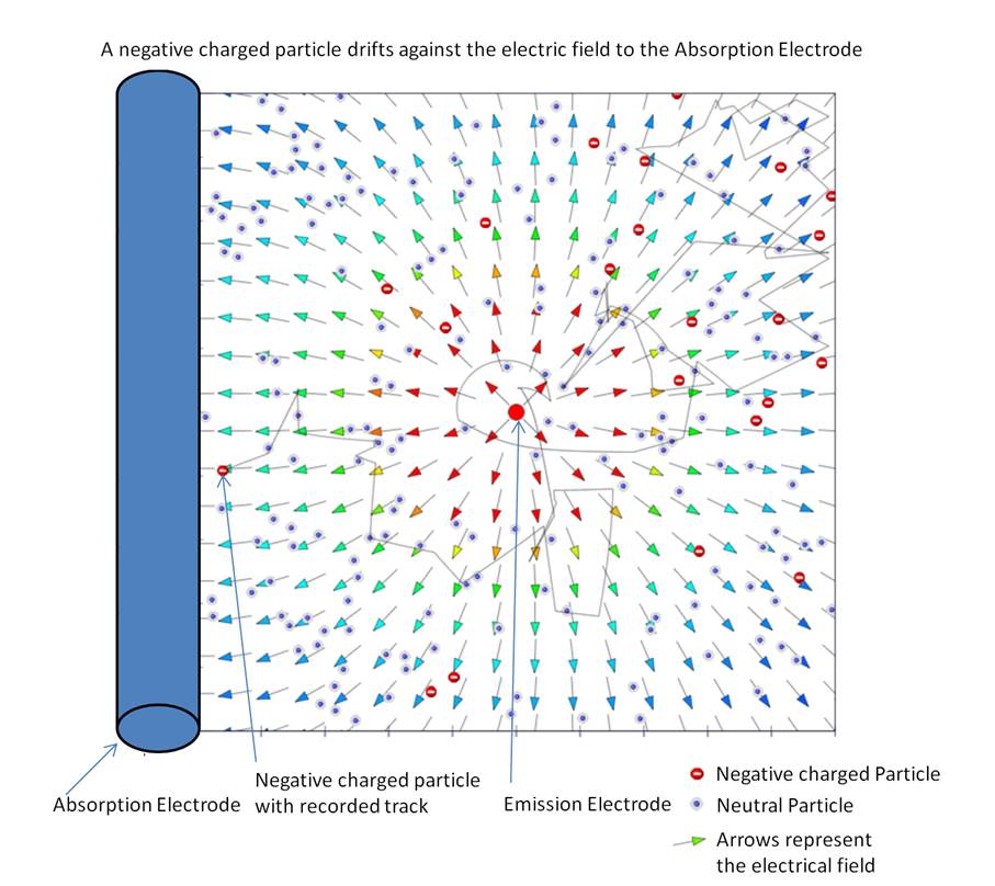
Figure 2: A negative charged particle drifts to the Absorption Electrode
Figure 2 originates from a computer simulation that confirms the functionality of the described process and calculates the resulting voltage.
The computer simulation works with the following real values:
1. Space geometry,
2. Mass and kinetic energy of the air particles,
3. Electrical load of the negative loaded air particles,
4. Acceleration of the negative loaded particles due to mutual repulsion (coulomb force) and
5. Acceleration of the negative loaded particles due to the electrical field.
The computer simulation works with the following simplified conditions that however do not change the basic functionality:
1. A horizontal cut is made through the constellation and the particles move only on this horizontal plane.
2. The number of particles per volume unit is strongly reduced. On an area of 20x20 cm 100 loaded and 100 not loaded particles are simulated
3. Each contact of a negative loaded particle with the absorption or emission electrode results in the absorption of the negative load. This condition prevents that a loaded particle bumps repeatedly towards an electrode and hence complicates the evaluation.
4. A (negative) voltage is applied between absorption and emission electrode. The ratio of the number of absorbed charges on the absorption and emission electrode specifies, whether the absorption of charges can conserve the voltage. A ratio greater or equal 1 means it can conserve the voltage. A ratio less than 1 means it cannot conserve the voltage.

Figure 3: two dimensional cut for the simulation
Figure 3 shows the setup of the simulation: a two dimensional cut is made through the constellation. The loaded particles move only in this plane. The emission electrode is located in the center, it consists of a needle. Since it stands vertically on the plane, the emission electrode is shown only as a (red) point. The absorption electrode is shown as cylinder on the left edge of the picture.
The simulation starts with 100 loaded and 100 neutral air particles evenly distributed in the constellation. The initial kinetic energy of the air particles is equivalent to the kinetic energy at 293°K, the direction of the initial movement of the particles is randomly chosen.
The negative loaded particles are influenced by the following forces and events:
1. The coulomb force
2. The electric field between absorption and emission electrode
3. The bumps with other loaded and neutral particles
4. The bumps against the walls of the container
Figure 4 shows a snapshot of the simulation with 100 negative loaded and 100 neutral particles. The applied voltage is drawn symbolically.

Figure 4: simulation with 100 negative loaded and 100 neutral particles
The result of the simulation is shown in Figure 5. The simulations were done with voltage values from 3 mV to 17 mV and 1mV increment. For each voltage value of the applied voltage 10 simulation runs were done and the results were averaged. If the ratio of the absorbed electrons cylinder /needle is greater or equal to 1, this means that the applied voltage can be at least conserved or increased. According to the simulation this is the case up to a voltage of about 10 mV. This result of the computer simulation of the conserved voltage of about 10 mV is remarkably near at the theoretical value of the voltage according to equation (4) of 12.7 mV.

Figure 5: Ratio Electrons Cylinder / Needle
5. Experiment:
Does it really work? A real experiment shall confirm the functionality. The emission electrode consists of a metallic needle. The absorption electrode consists of a metal cylinder with a length of 10 cm and a diameter of 3 cm. The constellation is comparatively setup like in Figure 1. The resulting voltage between emission electrode and absorption electrode Uae is measured potential free by an oscilloscope and transmitted wireless to a computer.
For a limited time, about 20 seconds, a voltage of about 30kV is applied at the opposite pole and removed again. Thereafter it lasts a few seconds and a voltage Uae of about 2 mV is built up between absorption electrode and emission electrode. The first 50 seconds are shown in Figure 6. The observed voltage Uae remains for some minutes but decreases slowly. In the second minute it is still present but decreased under about 1 mV, as can be seen in Figure 7.
The vibrations in the recorded voltage as seen in Figure 6 and Figure 7 result from the absorbed electromagnetic waves of the household network of 50Hz.

Figure 6: Resulting voltage Uae between absorption electrode and emission electrode, 0 to 50 seconds after start

Figure 7: Resulting voltage Uae between absorption electrode and emission electrode, 60 to 110 seconds after start
The result of the experiment does not yet show the voltage Uae
according to equation (4), which would be about U = - 0.0126 V. This still has
to be investigated. However a significant voltage Uae is observed
and it can be measured without big effort.
Also, the voltage Uae does not remain very long, namely roughly one
minute. This is probably because the electric potential at the two electrodes
against the opposite pole decreases slowly due to loss effects. This also
should be a field of improvement.
6. Conclusion:
The observed voltage between absorption electrode and emission electrode is the result of the conversion of thermal energy to electrical energy by means of emission, absorption and thermal drift of electrons. As already stated, no temperature difference is necessary here to convert thermal energy to electrical energy, the existence of thermal energy is sufficient.